What Is Servo Robot Seam Tracking and How Does It Work?

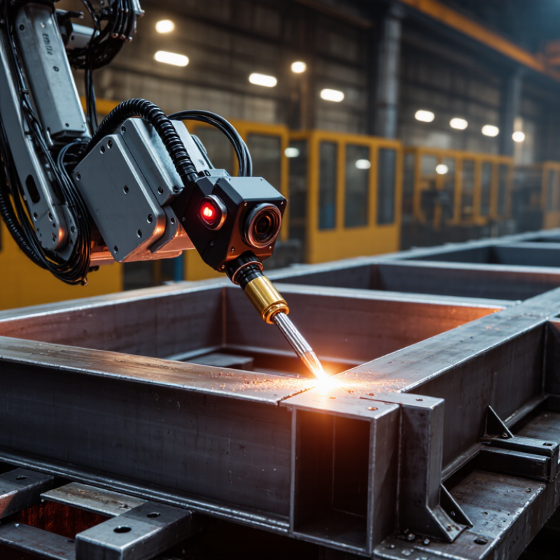
Servo robot seam tracking helps robotic welding systems follow a joint when its position changes during production. A laser sensor or vision camera scans the seam ahead of the welding torch. The controller compares the detected path with the programmed path. Servo motors then adjust the robot’s position, speed, or torch angle.

The principle sounds simple. The factory floor is not. Heat can pull metal out of alignment. Gaps may widen, narrow, or disappear beneath spatter. A sensor may also struggle with smoke, glare, dark surfaces, or poor calibration. John C. Lippold, a respected welding engineer and educator, offers a useful process-control principle: “A weld is only as reliable as the process that creates it.” That idea explains why servo robot seam tracking requires more than a smart sensor. It needs stable fixtures, correct sensing distance, clean optics, and carefully tested welding parameters.

In practice, the sensor may detect a V-groove on a steel frame while the robot moves several hundred millimeters per second. The system calculates the seam center and sends correction data to the servo controller. The torch follows the joint instead of relying only on fixed coordinates. This can improve consistency and reduce manual touch-ups. It cannot correct every defect. A badly prepared joint still creates problems.

Understanding servo robot seam tracking means examining the complete feedback loop. This article explores its sensors, control logic, calibration steps, practical benefits, and common limitations. Some results may appear imperfect. That is important. Real production conditions often reveal weaknesses that clean demonstrations hide.
What Is Servo Robot Seam Tracking and How Does It Work?

What Is Servo Robot Seam Tracking?

What Is Servo Robot Seam Tracking?

Servo robot seam tracking is a control method that keeps a welding tool aligned with a changing joint. The robot uses sensors to detect the seam’s actual position. Its servo motors then adjust speed, angle, and path during movement. Common sensing methods include laser vision, touch sensing, and through-arc feedback.

The process begins with calibration. A sensor scans the joint before or during welding. The controller compares the detected seam with the programmed path. If the joint shifts by two millimeters, the robot can correct its position instead of following an inaccurate line. This matters when parts contain distortion, gaps, or inconsistent fit-up. The International Federation of Robotics reported 541,302 industrial robots installed worldwide in 2023. That figure shows how quickly automated production is expanding, but it does not guarantee weld quality.

A practical limitation remains. Dirty lenses, reflective metal, vibration, and poor calibration can confuse the tracking system. A clean demonstration can mislead. Operators still need to inspect the joint and verify the correction limits. The American Welding Society’s 2023 workforce outlook projected a shortage of about 330,000 welding professionals in the United States by 2028. Servo tracking may reduce repetitive alignment work, but it cannot replace process knowledge. In real workshops, the best results usually come from combining sensor feedback, stable fixturing, and experienced supervision. Mistakes still happen. Better systems make them easier to detect.

What Are the Main Components of a Seam Tracking System?

A servo robot seam tracking system keeps a welding tool aligned with a joint as the robot moves. Its core component is a seam sensor, often using laser, vision, or touch detection. The sensor reads the joint’s position, gap, and height in real time. A narrow laser line may reveal a groove on a steel plate. Small surface changes still matter.

A signal processor converts that information into usable tracking data. The robot controller compares the detected seam with the programmed path. It then sends corrections to servo drives on the robot axes. These drives adjust speed, angle, and side-to-side movement with controlled precision. The welding torch, mounted at the robot wrist, must remain stable during these changes. Calibration connects the sensor’s measurements with the tool center point.

Software provides the tracking logic, monitoring screens, and parameter settings. Operators can set correction limits, response speed, and sensor delay. Cables, protective housings, and a rigid mounting bracket also influence reliability. In field use, vibration or welding spatter can distort readings. The system may then follow the wrong edge. That is why experienced technicians check alignment, clean the sensor window, and test a short seam before production. The process is not completely automatic. A poor calibration can remain unnoticed until the weld looks uneven.

What Is Servo Robot Seam Tracking and How Does It Work? – Main Components of a Seam Tracking System

System Component Primary Function Typical Data or Signal How It Supports Seam Tracking Common Considerations
Servo Robot Moves the welding or processing tool along the programmed path. Joint position, velocity, acceleration, and tool-center-point coordinates. Applies corrective motion while maintaining the required travel speed and tool orientation. Payload, reach, repeatability, axis configuration, and protection from heat or spatter.
Seam Sensor Detects the actual location and geometry of the joint. Lateral offset, height variation, groove profile, edge position, or surface image. Provides real-time feedback so the robot can compensate for part-position and seam deviations. Sensor range, resolution, sampling rate, viewing angle, fumes, reflections, and surface condition.
Laser or Vision Unit Projects or captures a profile of the workpiece and joint. 2D laser profile, 3D point data, contrast image, or feature coordinates. Identifies the seam center, edges, gap, height, and other geometric features without physical contact. Requires suitable optical alignment, calibration, shielding, and control of ambient light.
Signal-Processing Controller Converts sensor measurements into usable tracking corrections. Filtered position error, seam coordinates, confidence value, and alarm status. Filters noise, rejects invalid readings, calculates offsets, and prepares commands for the robot controller. Processing latency, filtering settings, synchronization, and fault-handling logic affect tracking quality.
Robot Motion Controller Combines the programmed path with live correction data. Position correction in X, Y, or Z; orientation correction; speed commands. Updates the robot trajectory while preserving coordinated motion and process speed. Coordinate-frame errors, communication delay, interpolation behavior, and correction limits must be controlled.
Tool Center Point and Mounting Defines the exact working point of the welding torch or process tool. Tool offset, approach angle, working distance, and sensor-to-tool distance. Ensures that sensor-detected errors are translated into accurate tool movement. Incorrect calibration can create systematic tracking errors even when the sensor is functioning correctly.
Welding or Process Tool Performs the welding, cutting, sealing, inspection, or dispensing operation. Current, voltage, wire-feed rate, gas flow, temperature, or material flow. Uses the corrected path to keep the process aligned with the joint or target feature. Tool geometry, heat generation, accessibility, consumable wear, and process stability are important.
Communication Interface Transfers measurements, corrections, status information, and commands between devices. Digital I/O, industrial Ethernet messages, serial data, or controller-specific feedback signals. Maintains synchronized information flow between the sensor, processor, robot, and process equipment. Bandwidth, deterministic timing, electrical noise immunity, and integration compatibility matter.
Calibration and Coordinate Frames Relates sensor measurements to the robot base, tool, and workpiece coordinates. Transformation matrices, reference points, offsets, and angular alignment values. Allows a measured seam deviation to be converted into the correct robot correction direction and distance. Calibration should be repeated after sensor movement, tool replacement, or significant mechanical impact.
Safety and Fault Monitoring Stops or limits operation when unsafe or unreliable conditions are detected. Emergency-stop status, sensor timeout, invalid data, collision signal, and protective-door status. Prevents uncontrolled motion or processing when tracking data is missing or outside acceptable limits. Safety functions must be designed and validated according to the applicable machinery and workplace requirements.
Basic Operating Sequence: The sensor detects the seam, the processing controller calculates the deviation from the programmed path, and the robot motion controller applies a limited correction to the tool position or orientation. This feedback cycle continues during the operation to compensate for workpiece tolerances, fixture variation, and seam irregularities.

How Does Servo Robot Seam Tracking Work Step by Step?

What Is Servo Robot Seam Tracking and How Does It Work?

Servo robot seam tracking begins with a programmed path and a calibrated sensing system. Before welding, a laser or vision sensor scans the joint. It detects the seam center, edge position, gap, and height. The controller compares these measurements with the planned path. Then comes calibration. The tool center point, sensor offset, and workpiece coordinates must match accurately. Small errors matter.

During movement, the sensor continuously reads the joint ahead of the torch. The controller converts this information into positional corrections. Servo motors adjust the robot’s motion along several axes. They may shift the torch sideways, raise it, or change its travel angle. The system also controls welding speed when the gap changes. This feedback loop repeats many times each second. The World Robotics 2024 report recorded 541,302 industrial robot installations worldwide in 2023. That scale shows why reliable sensing and motion control matter in modern production.

The process still needs human judgment. Reflections, spatter, dark surfaces, and poor lighting can confuse optical sensors. A clean calibration does not guarantee perfect tracking. Operators should test sample joints, review deviation data, and inspect the finished bead. The World Economic Forum’s Future of Jobs Report 2023 found that 44% of workers’ skills may be disrupted within five years. Seam tracking therefore requires practical training, not only automation. In real cells, technicians often adjust sensor sensitivity, filtering, and correction limits after observing several welds. Some imperfections remain. That is where process review becomes valuable.

What Is Servo Robot Seam Tracking and How Does It Work?

Typical processing sequence and representative response time in servo robot seam tracking

Servo robot seam tracking combines sensing, signal processing, position correction, and closed-loop motion control. A sensor detects the actual weld seam, the controller calculates the offset between the programmed path and the detected seam, and the robot continuously adjusts its position while welding.

The values shown are representative engineering response times in milliseconds. Actual timing depends on sensor type, controller settings, welding speed, seam geometry, and the communication cycle between the sensor and robot.

Which Sensors and Control Methods Enable Seam Tracking?

Servo robot seam tracking keeps a welding torch aligned with a joint, even when parts shift slightly. The system combines sensing, motion control, and measured correction. The International Federation of Robotics reported 541,302 industrial robots installed worldwide in 2023. This growth reflects stronger demand for repeatable automation, but reliable tracking still depends on site conditions.

Laser vision sensors scan the seam before or during welding. They detect gap position, height, and joint shape. Touch sensors use controlled contact to locate conductive workpieces. Through-arc sensing reads welding current and voltage changes while the torch moves.

Servo encoders then compare actual motion with the programmed path. A controller applies small corrections to position, speed, and torch angle. Proportional-integral-derivative control remains common, while adaptive control reacts to changing gaps.

ISO 9283 performance testing can help verify path accuracy and repeatability. However, laboratory accuracy may not survive smoke, spatter, vibration, or reflective metal.

Tips: Calibrate the sensor at the working distance, not on a clean bench. Keep the scan window free from heavy spatter. Use a slow search movement near the joint. Set correction limits before production begins.

In my experience, the first pass is rarely perfect. A bright seam can confuse vision software. A touch probe can also damage a thin edge. Record missed detections, then adjust filtering and approach speed. A strong system does not hide uncertainty; it measures it and responds safely.

Where Is Servo Robot Seam Tracking Used?

Servo robot seam tracking is used where weld paths shift during production. Automotive body shops apply it to doors, frames, exhaust parts, and battery enclosures. Small gaps, heat distortion, and inconsistent fixtures can move a joint several millimeters. A vision or touch sensor detects the seam, then the servo controller adjusts the torch position during welding.

It also serves heavy equipment, agricultural machinery, railcar production, shipbuilding, and structural steel fabrication. These sectors often handle long joints, thick plates, and irregular surfaces. On a factory floor, the sensor may follow a bright groove beside a weld pool. In another cell, it may track a joint through dust, reflections, or changing material colors. That difference matters. One sensing method rarely performs equally well everywhere.

The International Federation of Robotics reported 541,302 industrial robot installations worldwide in 2023, with 4.28 million robots operating globally. Its World Robotics 2024 report does not isolate seam-tracking systems, but the figures show the expanding automation base around them. Practical experience suggests that tracking improves consistency, especially on repeated joints. It cannot repair poor fixture design or badly prepared edges. That is the uncomfortable part. Engineers still need calibration, clean sensor windows, and regular verification. In demanding plants, operators should review missed detections instead of trusting every correction blindly.

SERVO-ROBOT Inc
Privacy Overview

This website uses cookies so that we can provide you with the best user experience possible. Cookie information is stored in your browser and performs functions such as recognising you when you return to our website and helping our team to understand which sections of the website you find most interesting and useful.